Select a file to view it.
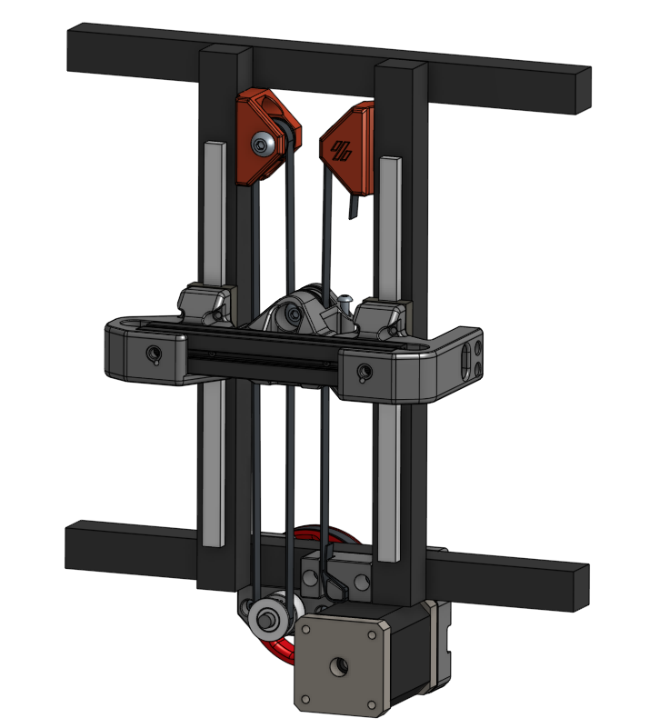
There already are belt-driven mods like theFPVGeek's V0 Z Belt mod and MathematicalPotato's adapted version for V0.1. This is my attempt to combine the timing belt with a movable pulley system.
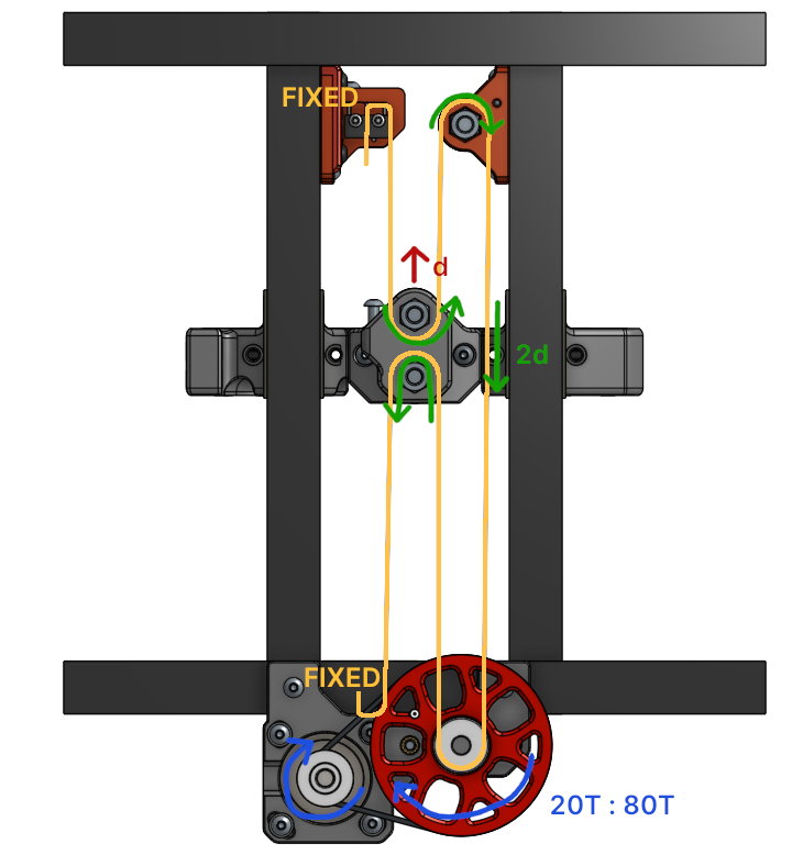
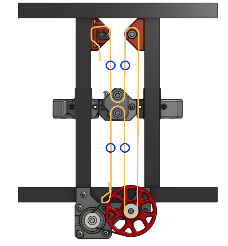
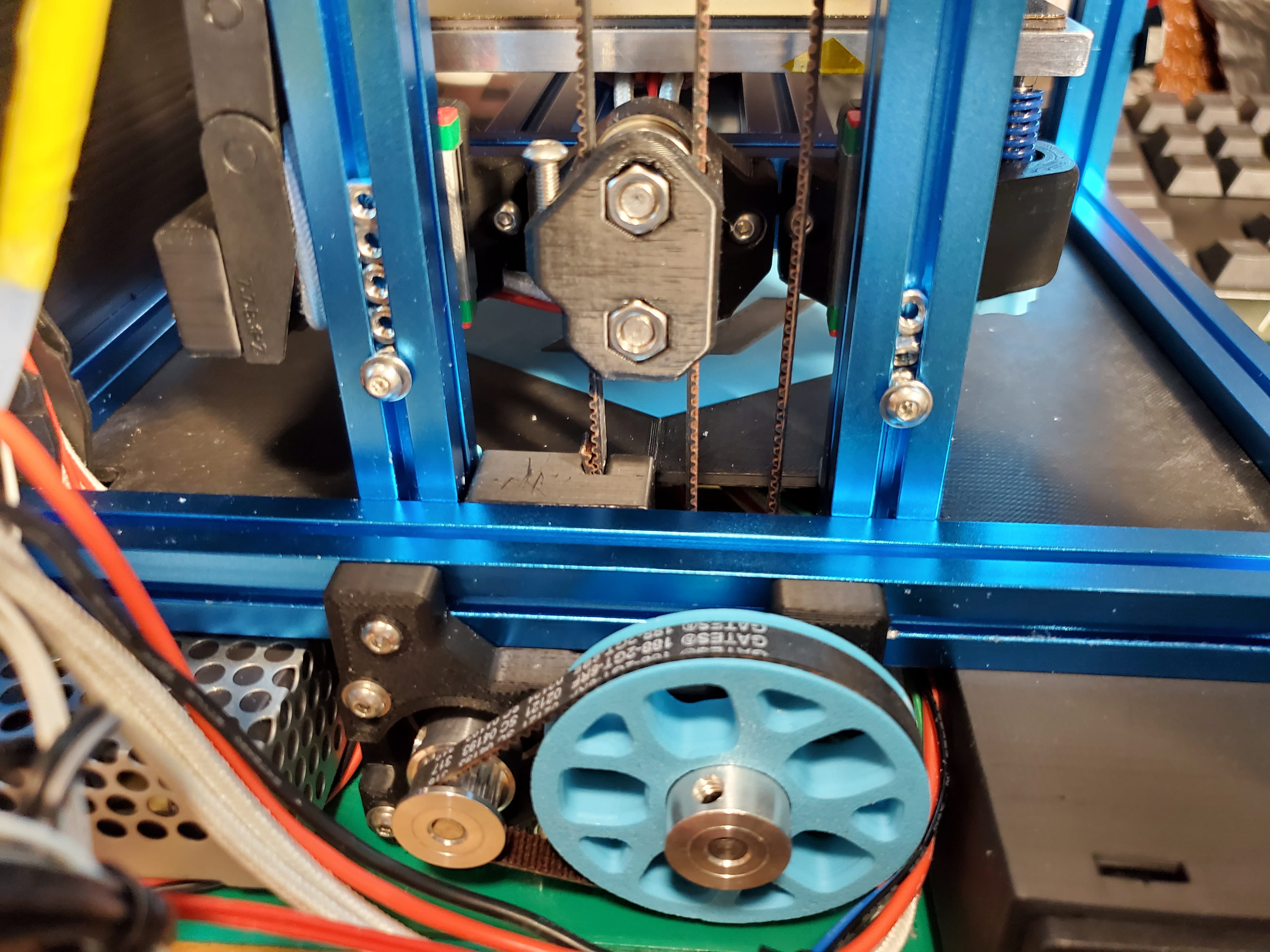
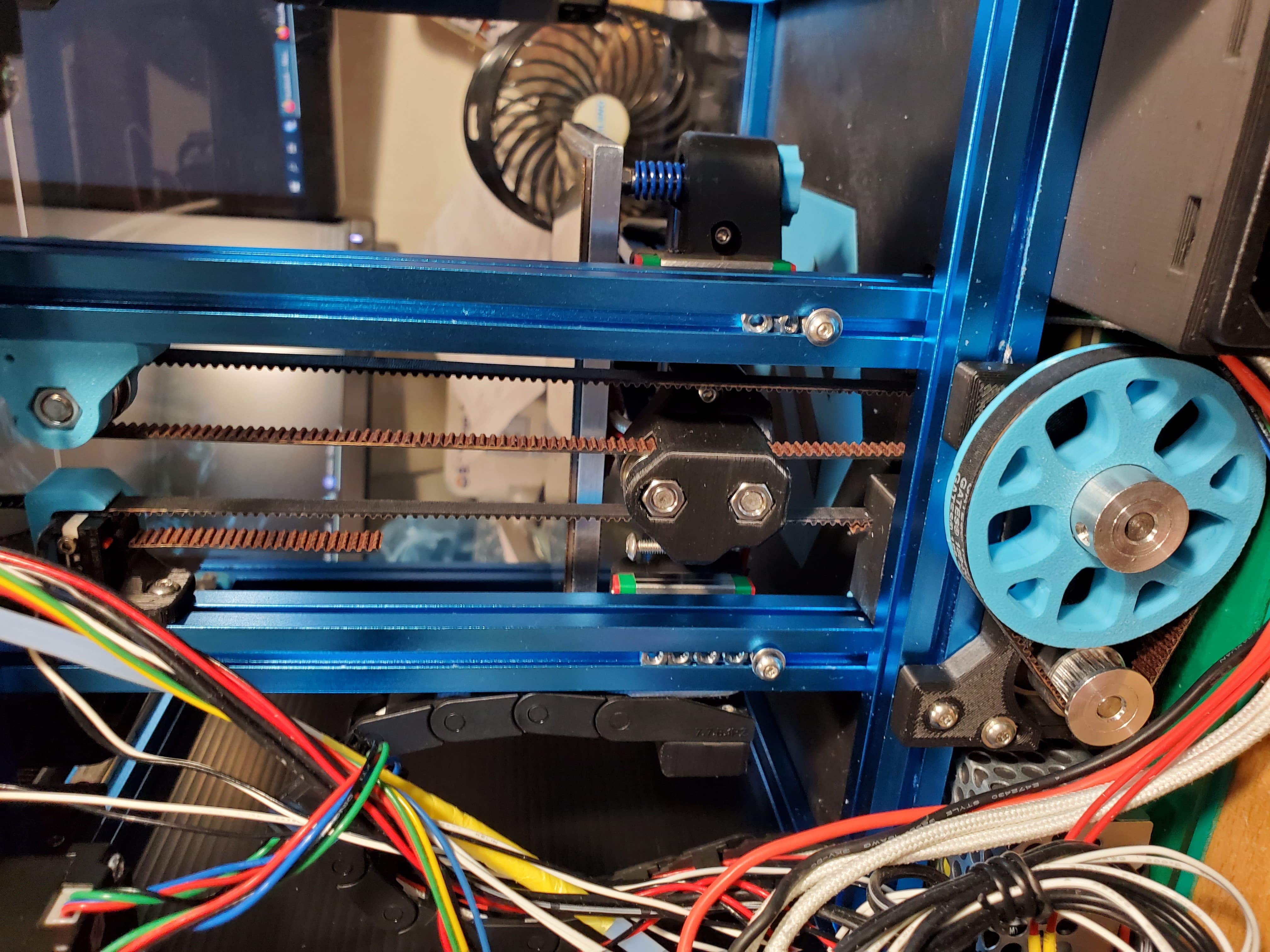
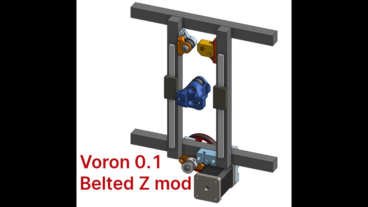
As shown in the following figure, the belt drive on the motor is a 20T:80T system.
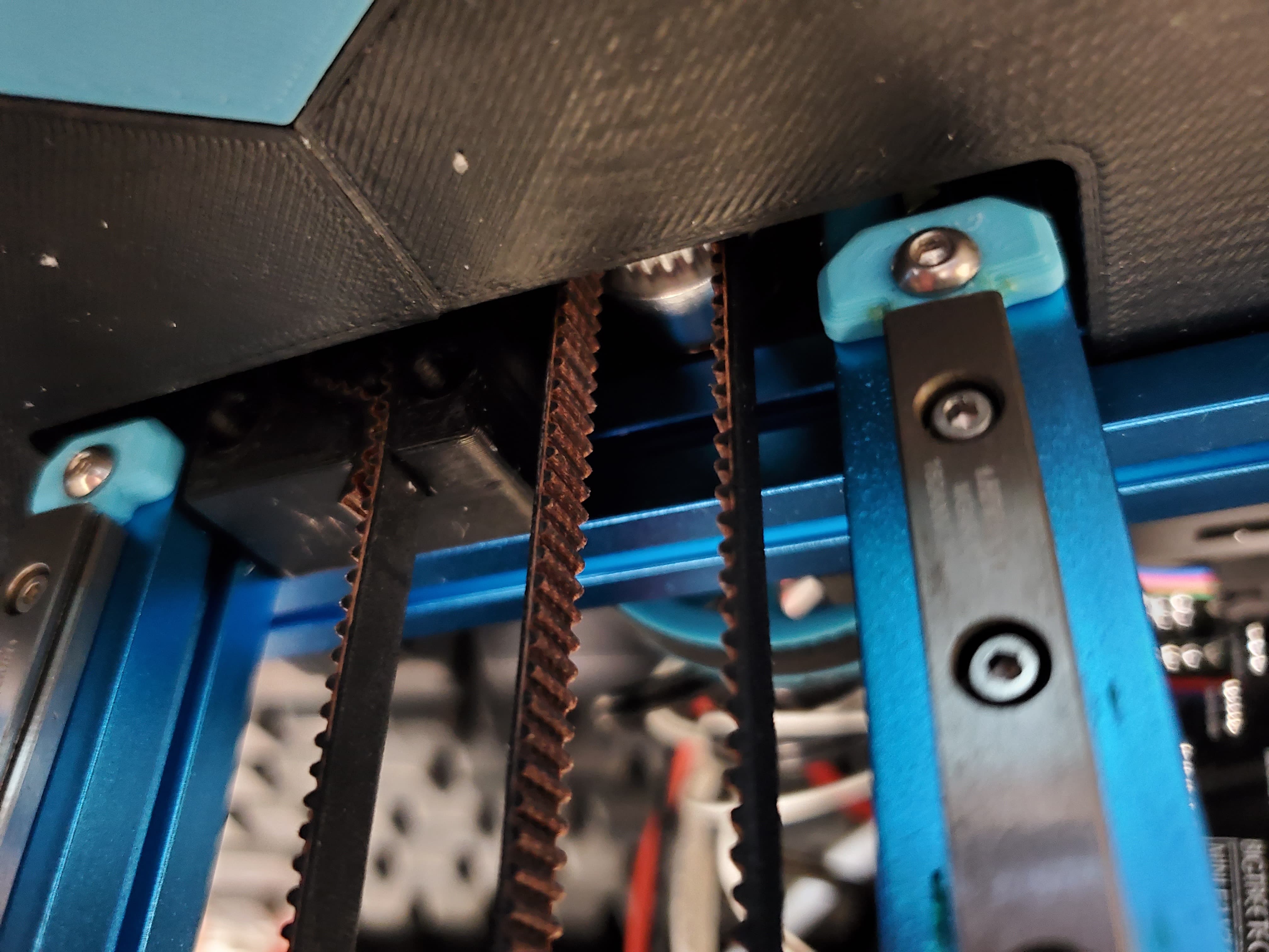
The driven belt path with constant belt length is a movable pulley system with the two belt ends fixed at the upper and lower parts of the frame.
Note the places that need threaded inserts. You can pre-apply them.
M4-like driving gear
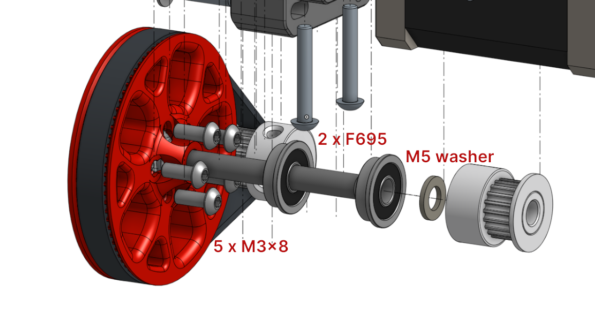
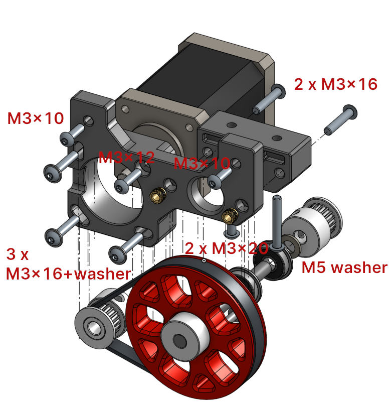
This is very similar to Voron M4 extruder. Just mind the placement of the F695 bearings. You can refer to Nero's video guide for details about assembling Voron M4.
The 80T_gear_7mm.stl provided is a thinner version of the M4 toothed gear with 7mm of tooth width instead of 9mm to save a little weight and space. Both should work here.
Bed Holder (for Stock V0.1)
Kirigami Bed Holder
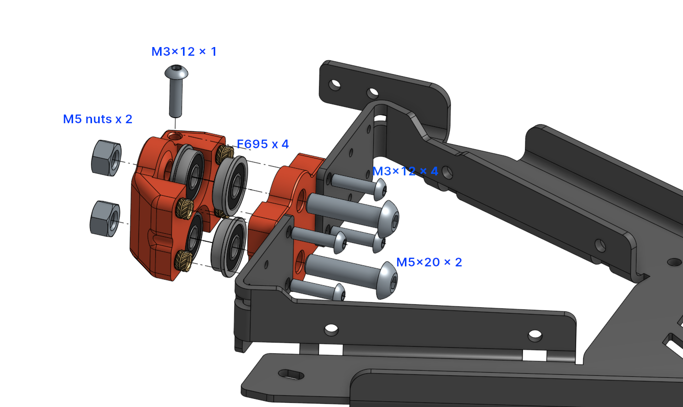
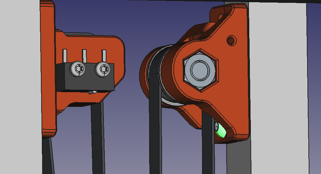
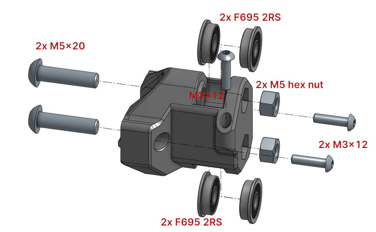
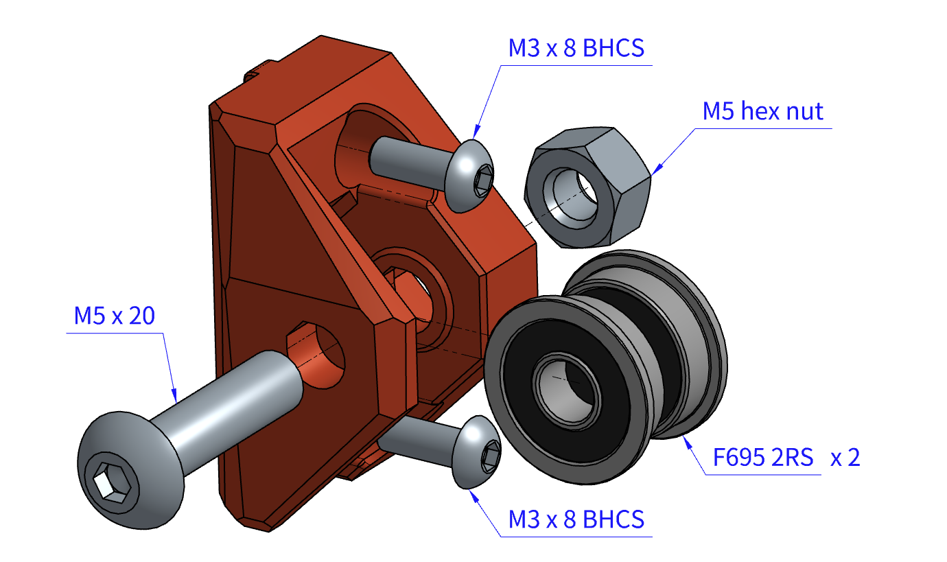
Top Idler
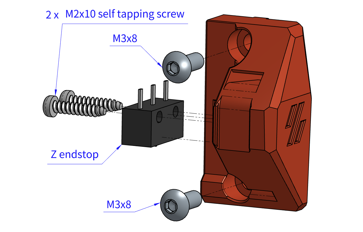
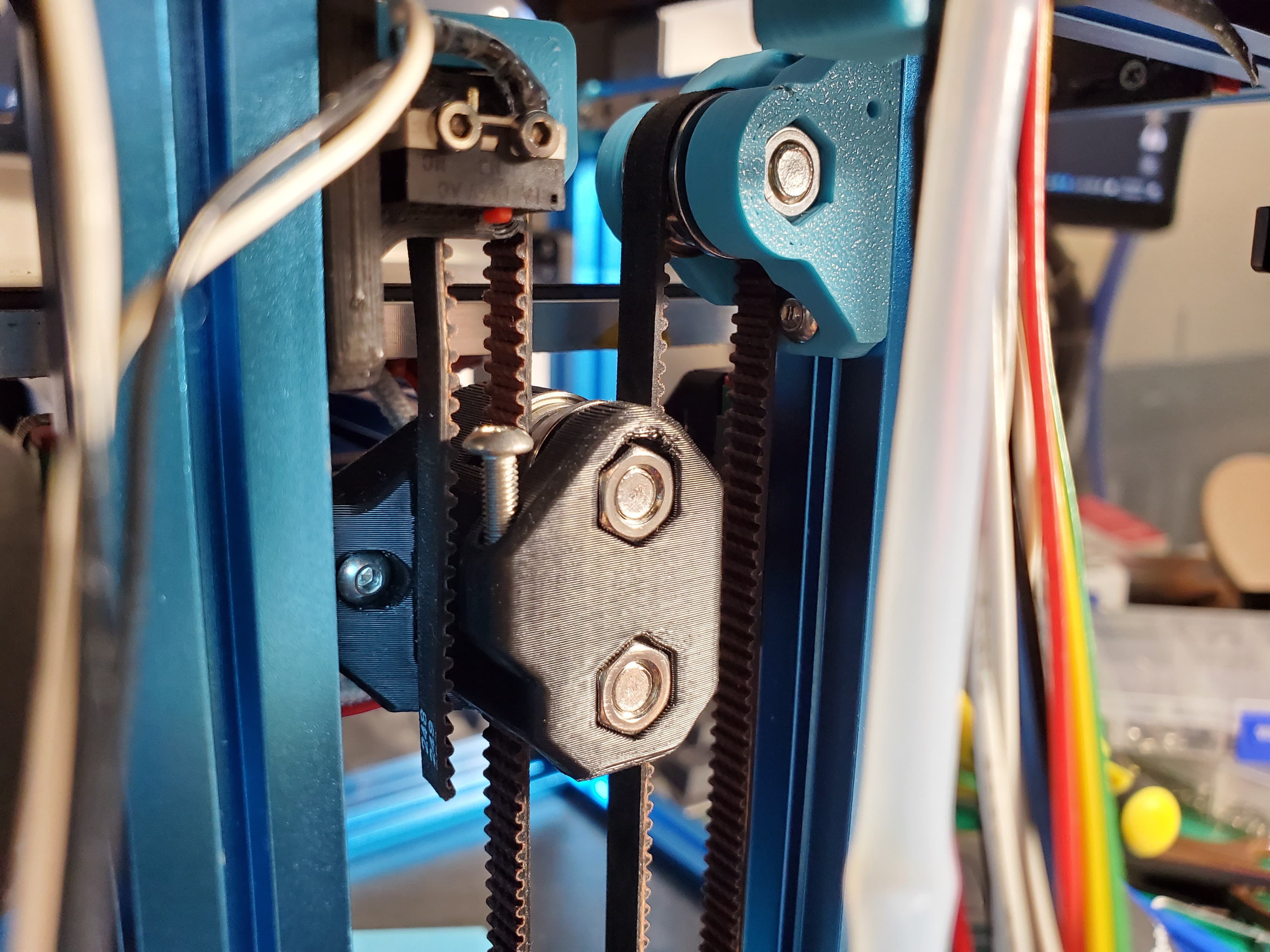
Top Endstop Mount
Use the stock Z endstop and the two M2 self tapping screws.
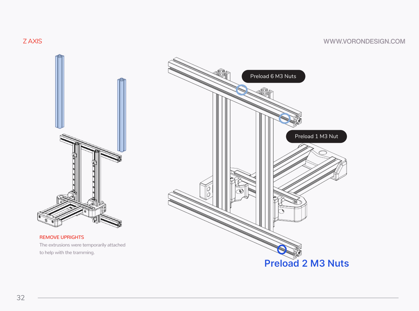
Preload 2 M3 nuts at the marked slot on page 32 of the manual.
(Note: If you don't want to take the frame apart, it can be mounted without these two nuts but it may be less rigid. Don't tighten the belt too much then. NOT TESTED!)
Make a loop on one end of the belt and press it into the printed part. Then mount the printed part to the frame with 2 M3x8 screws.
Mount each component to the frame (don't fully tighten up yet). There should be preloaded nuts if you followed the V0.1 manual. The two upper components and their nuts can be slid in from the top.
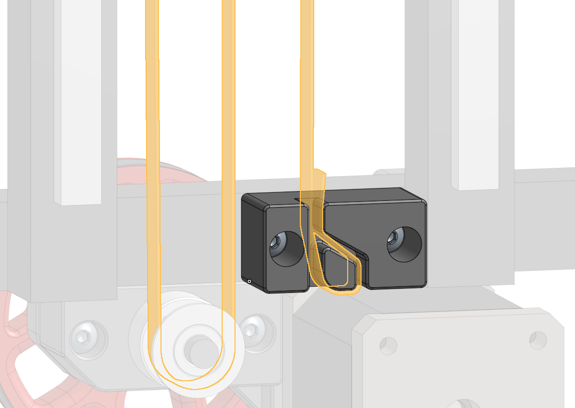
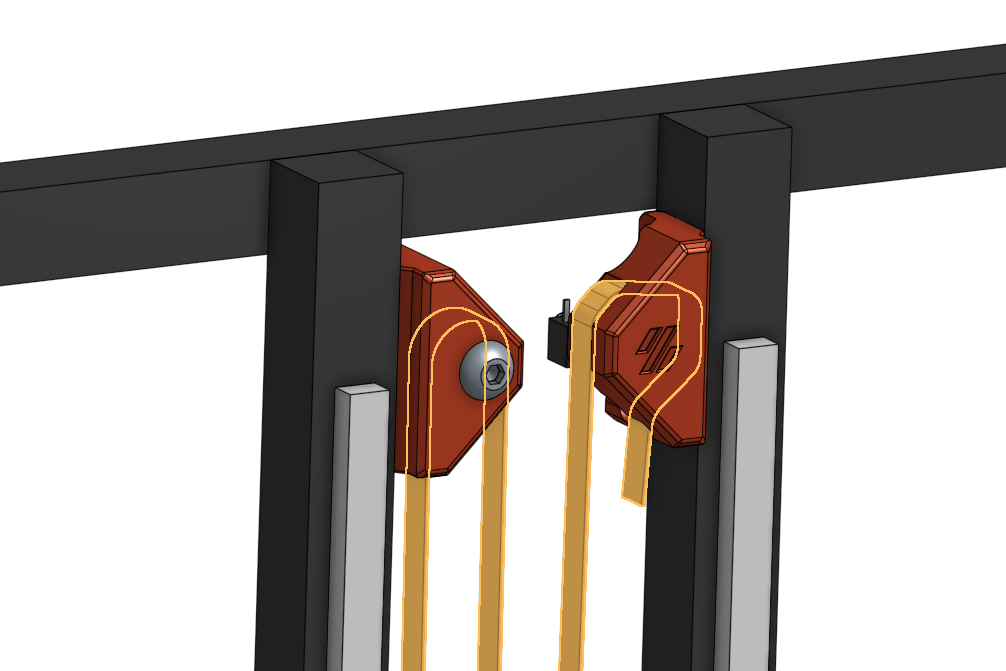
Route the belt path as shown in the mechanism figure.
The upper belt end should go through the upper_belt_end.stl as shown below.
(Tip: Temporarily lower the upper idler to have enough belt length to get the belt end though the holder.)
Slightly adjust the position of each component so the bed holder is at the middle of the extrusion and the four marked segments of the belt are as parallel to the Z rails as possible.
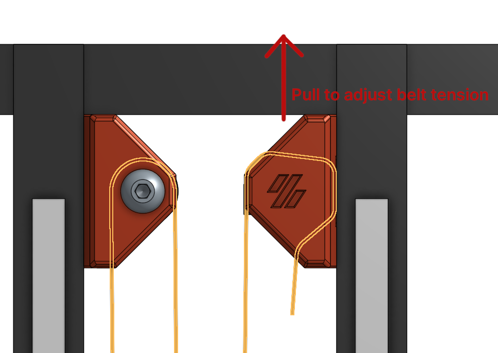
Belt tensioning.
First mount the top endstop holder about 2-4mm lower from the top horizontal aluminum extrusion. Loosen the mounting screws and pull the excessive belt through the holder.
Slightly tighten the mounting screws so the belts doesn't slip out while the endstop mount is still moveable. Pull the endstop holder upward to adjust the belt tension then fully tighten the mounting screws.
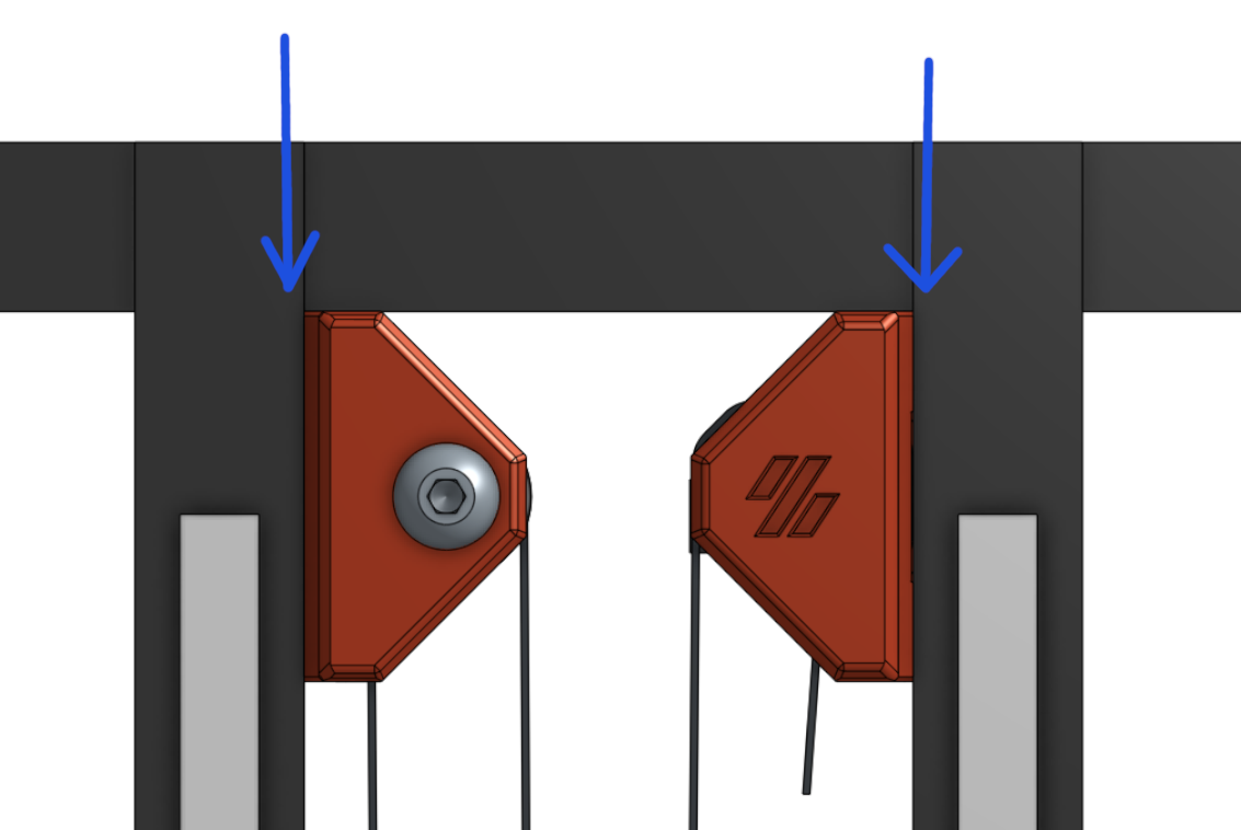
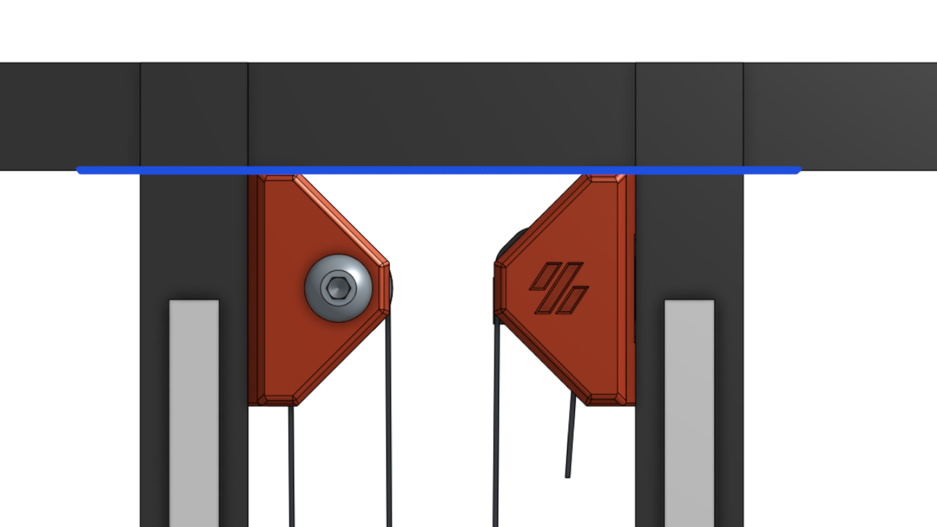
(Note: As marked in the figure, the top idler mount and endstop mount should be about flush with the bottom of the horizontal aluminum extrusion. Make sure the mini-AB doesn't crash into the screw heads or printed parts.)
[stepper_z]
step_distance: 0.0015625
[stepper_z]
rotation_distance: 40
gear_ratio: 80:20, 2:1
Here's a video of testing the bed motion:
Redesigned the upper parts (again) for the following purpose: