Mount Adafruit NeoPixel Sticks on the V0 Y-rail Extrusions
- Add controllable RGB(W) LEDs to your V0
- No heatset inserts required
- Compatible with NeoPixel Sticks from Adafruit
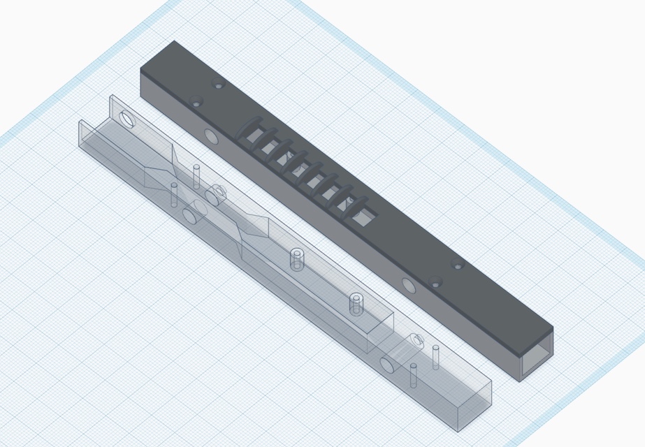
- Large cavity inside the body makes wire management easier
- Light guides prevent LEDs from blinding you
- Designed with Timmit99's V0 Umbilical in mind (not required)
Inspired by the mod from JNP
BOM
- Printed parts
- (2) Adafruit NeoPixel Stick
- (8) M2×6 flat head - to mount covers
- (4) M2×8 SHCS/BHCS - to mount the PCBs
- (4) M3×6 SHCS/BHCS - to mount the assemblies to the Y-rail extrusions
- (4) M3 nuts - to mount the assemblies to the Y-rail extrusions
- (2) JST-XH connector plug, 4-position - to allow for easy disconnection (optional)
- 22awg wire
Assembly
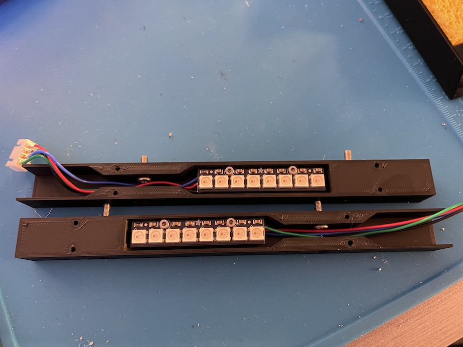
- Solder wires of appropriate length onto the back of each PCB (VDC, GND, DIN, and DOUT)
- If using JST-XH as disconnects, solder the other ends of the wires to 4-position (male) connectors - the connector should fit inside the body cavity once assembled
- Mount the PCBs inside the printed bodies using M2×8s
- Don't install the printed covers at this stage
Installation
- Insert 2× M3 nuts on the bottom side of each Y-rail extrusion - requires partial frame disassembly if already assembled
- For the wire path, you have two choices:
- Drill 1/4" holes in the midpanel where the printed bodies comes into contact with the midpanel and route the wires through that
- Route the wires through the opening on the "top" of the printed body, through the slot of the extrusion, and over the midpanel
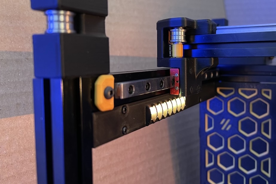
- Install the printed and assembled body to the Y-rail extrusions using 2× M3×6s and the previously inserted M3 nuts
- Route wires and fold excess wire inside the body cavity (see wiring below)
- Install the printed covers using 4× M2×6 flatheads (SHCS/BHCS might also work - check clearance with the gantry )
Wiring
- If using Timmit99's V0 Umbilical frame PCB, connect the pixel strips to Strip1 and Strip 2.
- Pay attention to pin ordering!
- If connecting directly to a compatible controller, you have to chain the data signal between the left and right assemblies
- Choose either the left or right assembly to be the first in the chain
- The Controller's neopixel data output pin will connect to the
DIN of that "first" assembly
- The
DOUT of the "first" assembly must connect to the DIN of the "second" assembly
VDC and GND of both assemblies must be connected to the Controller's neopixel VDC and GND pins
- Some Controller boards (e.g. SKR) require a capacitor and resistor - SKR Neopixel Breakout Board link1 link2
Klipper Config